How To | Connect stereo outputs to mono input
Learn how to connect a stereo output device to a mono input device for optimized sound.
Procedure
It is not uncommon to try to connect a stereo line-level or headphone-level output device, such as a smartphone, PC audio output, or a CD player, to an input channel of some product. The stereo outputs of the device are typically unbalanced signals, either presented as a pair of RCA connectors (usually red/right and white/left) or are a single 1/8" (3.5 mm) stereo TRS plug (usually Tip/Left, Ring/Right, with a common Ground wire or shield). Quite often it is the stereo headphone jack of the source device. The input device is usually balanced XLR or euro-block connectors in pro equipment, but it could also be an unbalanced RCA input connector. For this discussion, we'll assume the input is a balance XLR or euro-block ("Phoenix") connector.
Ideally, since these stereo outputs are two distinct signals, they should be connected to two separate inputs on the receiving device. Since these are unbalanced, appropriate wiring practices prevail with regard to wiring the balanced inputs, covered in other numerous KB articles and application guides.
There are occasions, though, when someone wants to treat that source device, perhaps a smart phone connection with cable terminating with an 1/8" stereo plug, as a single (mono) audio input. You CANNOT simply wire it directly to a single balanced input! This signal is a stereo signal to start with. You need a way to "mix" those two signals into one mono signal to feed the line-level input.
Very often, an inexperienced audio person will attempt to wire the stereo pair's three wires directly to the input's 3-pin balanced input. They dutifully connect one signal to the plus terminal, the other signal to the negative terminal, and the shield to the ground terminal. When the system is then turned on, they find they have very little signal, if any, available at the input section of the receiving device. And any signal that might be present is lacking in any low-end frequency response, i.e., it "sounds tinny" to them.
What they have essentially done is wired the two unbalanced outputs to a balanced input's inverting and non-inverting connections (which is what a balanced input is expecting). The two signal are now exactly 180 degrees out of phase (or reversed polarity) to each other, thereby canceling each other! Typically, low frequencies (drums, bass, keyboards, etc.) and very often lead vocals are "centered" equally between the left/right outputs. Now that the left/right are opposing each other, those centered/common signals are essentially cancelled. This is known as "common mode rejection" which is exactly why balanced inputs reject noise and interference so well. For long runs of balanced cable, any such noise picked up by both wires is cancelled at the balanced input stage. The only signals which make it through are those left/right signals which are different from each other.
The tech can hear that this does not sound right, so the tech Googles for how to connect unbalanced outputs to balanced inputs. The tech reads that the correct way to wire an unbalanced signal to a balanced input is to put the signal wire onto the positive terminal, and the ground shield to the negative terminal with a jumper to the ground terminal of the balanced connection.
The tech decides to "merge" or parallel wire the two unbalanced left/right signals the "proper" way to an balanced input. The tech dutifully wires BOTH of the left/right "hot" leads to the input's positive terminal, and the common shield to the negative terminal, with a jumper from the negative terminal to the ground terminal. Or they use a commonly available "Y" connector or cable to join the two signals first into one common signal, then wire the "output" of the Y connector to their balanced input. This actually sounds better than before, but is still incorrect.
Wiring this way may indeed sound better than the earlier "reversed polarity" wiring, but in the long run may lead to less-than-optimal signal at best. At worst, this could damage the stereo source device, because there is no electrical isolation between the two outputs - one output "sees" the other. This could lead to unintended distortion or even output stage damage. These outputs typically are low impedance signals expecting a relatively higher impedance connection downstream. But paralleling the two means each channel is loaded by the low impedance of the other channel. The correct solution is to provide some sort of mixer circuit, so each output signal sees a relatively higher impedance and those two signals are then properly summed/mixed to a single mono output.
The solution can be either an active mixer (expensive) or a simple inactive/passive mixer circuit (inexpensive). The passive mixer should be transformer-coupled, but even simple resistor-based mixer circuits are a VAST improvement over the directly-paralleled coupling of the stereo signals. And the resistor-type "circuit" is really just a few inexpensive, readily-available resistors. The resistors can be wired such that they could be fit INSIDE the XLR or directly onto the euro-block connector. There are also ready-made devices which properly connect two unbalance outputs to a balanced input. While not as inexpensive as a few resistors, they are off-the-shelf solutions and certainly less expensive than having to use an active mixer.
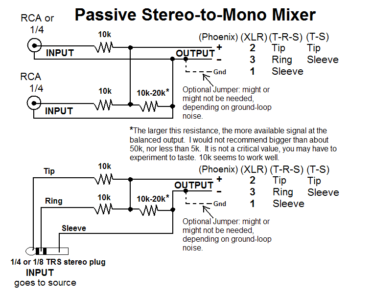
Here is a wiring diagram showing three resistors providing this passive mixer circuit. The circuit is simple, inexpensive, and can be made small enough to fit inside an XLR backshell or mounted onto a euro-block connector:
Note
The inline resistor to ground is to impedance match the output OP amp and not create back flow. This protects these integrated circuits from "burning out." An added benefit is this reduces crosstalk
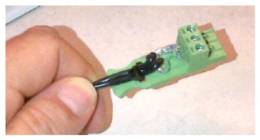
Here is how one might attach those resistors to a Phoenix/euro-block connector it is suggested to use heat-shrink tubing insulation or a similar method to help prevent inadvertent wire shorts:

And here is a photo of the actual wiring in use:
For those who aren't inclined to "roll their own" resistor circuit, here is an off-the-shelf solution. Google for others but make sure the solution is either resistor or transformer-based, or both. The example is not an endorsement, just suggestions: