How To | Example GPIO Configuration for Fire Alarm Relay with Digital TTL
Learn to configure GPIO for a fire alarm relay using digital TTL.
Procedure
Many installations include safety requirements for a system-wide mute when a fire alarm is triggered. In the case of Q-SYS installations, this is typically accomplished using GPIO available on our Cores and/or I/O endpoints.
The steps below describe common settings for a system using Digital TTL relays.
- Add GPIO-input into your design for your connected device.
- Assign the GPIO input property to digital input (this will trigger the relay).
- Wire the GPIO digital input to the system mute control pin.
The first example shows a system with a low output when the alarm is off.

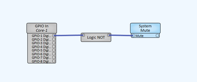
Depending on the triggering system, the output may be high when the alarm is in an off state. In this situation, a “logic not” will be needed as shown below.
Note
Regarding Fire Marshal code interpretation and standard accepted implementations, the levels of fail safes, etc. can vary by region, municipality, or individual AHJ.