Awareness | Digital Input (TTL3) configuration and behavior for QIO-GP8x8
Learn how to use a Digital Input (TTL3) to control the QIO-GP8x8 digital input/output device.
Information
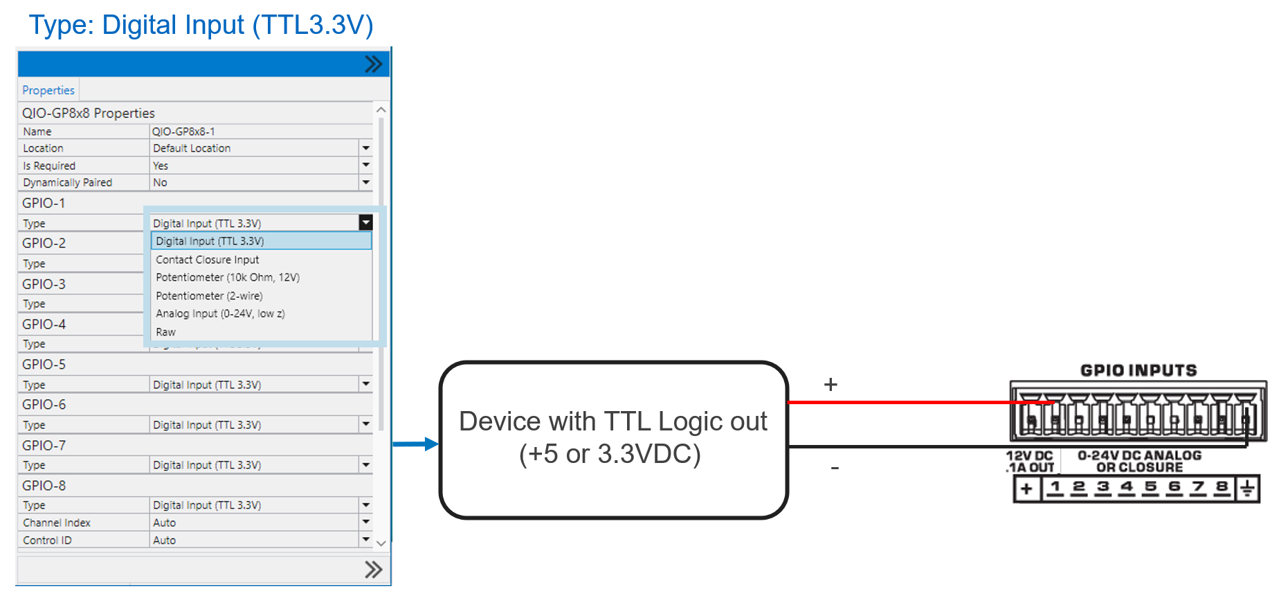
The following is an example of general configuration and behavior for Digital Input (TTL3) setup on the QIO-GP8x8.
This setup is typically used to interface with external devices with a TTL Logic output.
Requirements
- Logic output of upstream device should be +5 or +3.3 VDC signal in “high state”.
- YS input is 5 VDC tolerant.
- Threshold for “low state” is 2 VDC.
Note
In this configuration, the external device must provide a voltage when the input is “high”. Q-SYS does not provide TTL voltage at the input stage.
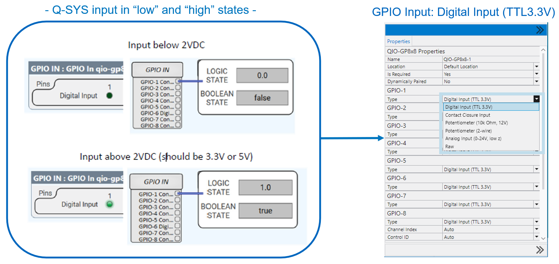
Here is Q-SYS GPIO input set to Digital Input TTL -> in Low and High states → when the input is below 2 Volts DC -.> Logic State = 0 and Boolean State = False, -> and above 2 Volts DC -> more like 3.3V or 5V -> Logic State = 1 and Boolean state = True.