Awareness | PL-LA Series Rigging Guide
This guide provides valuable information on rigging procedures and best practices for PL-LA Series equipment, enhancing awareness and ensuring safe rigging operations. Whether you are a novice or experienced rigger, this guide will help you navigate the complexities of rigging with confidence.
Information
This article will cover the various rigging and installation guidelines for the PL Series loudspeakers.
More information may be found in the PL-LA User Manual.
Attention
The following information should be considered before installation.
Safety
General Rigging Safety Precaution
General Rules for Suspension
- Consult a professional mechanical or structural engineer, licensed in the jurisdiction of the sound system installation, to review, verify, and approve all attachments to the building or structure.
- Employ the services of a certified, professional rigger for hoisting, positioning, and attaching the equipment to the supporting structure.
- Correct use of all suspension hardware and components is imperative in sound system suspension and deployment.
- Always calculate suspended loads before lifting to ensure suspension components and hardware are used within their respective load limits.
- Consult local codes and regulations to fully understand the requirements for suspended loads in the venue in which equipment will be suspended.
- Use only dedicated PL-LA Series rigging hardware as described in this manual for suspending a loudspeaker array. Further details can be found below.
- Be absolutely certain of the integrity of any structural member intended to support suspended loads. Hidden structural members can have hidden structural weaknesses.
- Never assume anything! Owner or third-party-supplied suspension attachment points may not be adequate for suspending the loads.
- Before lifting, always inspect all components (enclosures, suspension brackets, pins, frames, bolts, nuts, slings, shackles, etc.) for cracks, wear, deformation, corrosion, missing, loose, or damaged parts that could reduce the strength of the assembly. Discard any worn, defective, or suspect parts and replace them with new, appropriately load-rated parts.
Shock Loading
When a load is moved or stopped, its static weight is magnified. Sudden movements can magnify the static weight several times. This is called “shock loading.”
The effects of shock loading can be instantaneous, or it can remain undetected. Proper preparation for shock loading requires careful planning and knowledge of equipment, suspension, and lifting practices. Shock loading is most often the result of lifting and installation, but natural forces (winds, earthquakes, etc.) can create shock loads several times the static load.
Shock loading poses a danger to equipment and workers. Because of this, structures and suspension equipment must be capable of supporting several times the weight of the suspended equipment.
PL-LA Rigging
Rigging Categories
Certification of the PL-LA Series rigging system has been analyzed by an independent structural engineering firm to certify some worst-case configurations. The Categories covered by the certification include the following Array deployments:
- Array Frame, Loudspeaker without Pullback Bar
- Array Frame, Loudspeaker with Pullback Bar
- Array Frame, Subwoofer, and Loudspeaker without Pullback Bar
- Array Frame and Subwoofers only
- Loudspeaker array with two Pullback Bars
Array Restrictions
- The splay angle for each speaker must always be equal to, or greater than the splay angle of the speaker directly above.
- The Total Splay angle in an array should never exceed 62.5° for PL-LA8 and 70° for PL-LA12.
- WLLs are based on simply suspended arrays using the available Array Frame pick points to angle or aim the array up or down. Notwithstanding the use of a Pullback Bar, any method or means used to angle the array up or down beyond these simply suspended angles may reduce the FOS.
- All Loudspeaker rigging Certified only for Q-SYS array frames and Pullback Bar. Assembling with other structure is out of scope.
FOS changes according to the Total Splay Angle and Frame Angle. The following tables have been computed with the mentioned parameters. If the tilt or Total Splay of your particular array is above those parameters the Factor of Safety rating will be impacted.
Warning
Do not substitute the Shoulder Bolts included with the Loudspeakers, replace them only with the Q-SYS part SC-000777-01 or equivalent.
Maximum Suspended Load (WLL)
PL-LA8 WLL
Working Load Limits (WLL) | ||||
|---|---|---|---|---|
Model |
Individual Component Weight |
7:1 Safety Factor |
10:1 Safety Factor |
Notes |
| PL-LA8-AF | 13.6 kg / 30 lbs | |||
| + PL-LA8 Array | 12.4 kg / 27.3 lbs |
15 PL-LA8 217.7 kg / 480 lbs |
12 PL-LA8 169.2 kg / 373 lbs |
Max Total Splay angle of 62.5° |
| PL-LA8-PB Pullback Bar | 1.6 kg / 3.4 lbs | 173.7 kg / 383 lbs | 121.6 kg / 268 lbs |
15 PL-LA8 at FoS 10:1 See Restriction in “Pullback Bar” |
| PL-LA8 M10 Pullback Point | Built into rear of product | 92.1 kg / 203 lbs | 64.4 kg / 142 lbs | |
| Double Pull Back Deployment | 8 PL-LA8 |
|||
| LA-KIT-I (1) | 4 PL-LA8 |
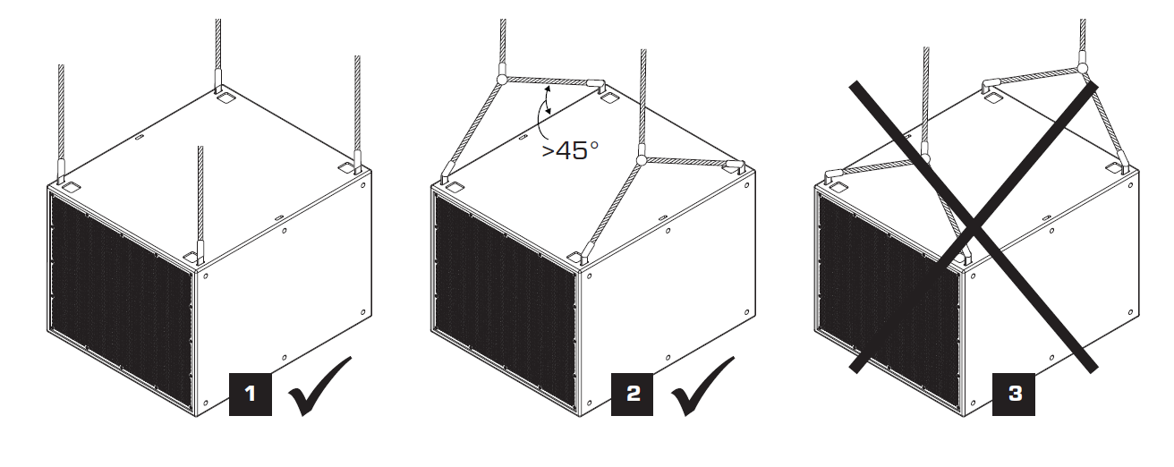
Included bridled angle to be 90° or less. | ||
PL-LA12 WLL
Working Load Limits (WLL) | ||||
|---|---|---|---|---|
Model |
Individual Component Weight |
7:1 Safety Factor |
10:1 Safety Factor |
Notes |
| PL-LA12-AF | 14.5 kg / 32 lbs | |||
| + PL-LA12 Array | 19.5 kg / 43 lbs |
14 PL-LA12 300.3 kg / 662 lbs |
10 PL-LA12 214.1 kg / 472 lbs |
Max Total Splay angle of 70° |
| + PL-SUB18 Column | 46.3 kg / 102 lbs |
10 PL-SUB18 477.2 kg / 1052 lbs |
8 PL-SUB18 384.6 kg / 848 lbs |
Max Tilt Angle +/- 5° |
| + PL-SUB18 + PL-LA12 |
3 PL-SUB18 + 11 PL-LA12 377.8 kg / 833 lbs |
3 PL-SUB18 + 7 PL-LA12 296.2 kg / 653 lbs |
Max Tilt Angle +/- 5° Max 1 SUB rear facing |
|
| PL-LA12-PB Pullback Bar | 2.1 kg / 4.6 lbs | 161.9 kg / 357 lbs | 113.4 kg / 250 lbs |
12 PL-LA12 at FoS 10:1 See Restriction in “Pullback Bar” |
| PL-LA12 M10 Pullback Point | Built into rear of product | 80.3 kg / 177 lbs | 56.2 kg / 124 lbs | |
| Double Pull Back Deployment | 8 PL-LA12 |
|||
| LA-KIT-I (1) | 3 PL-LA12 |
Included bridled angle to be 90° or less. | ||
Information about EASE GLLs may be found here.
Spare Parts
Any spare parts can be purchased from the QSC Spare Parts web store or QSC customer care
| Q-SYS Ref. | Designation | |
|---|---|---|
| CH-008429-01 | REAR LINK | 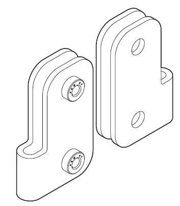 |
| CH-008430-01 | Y-LINK | 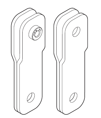 |
| CH-008428-01 | STRAIGHT LINK | 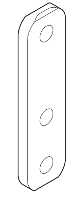 |
| SG-000728-01 | INPUT COVER FOR IP65 (includes gasket, screws and label) |
 |
| CO-000981-01 | CONNECTOR 4 POLES |  |
| SC-000814-01 | SCREWS FOR INPUT COVER | M4-10mm screw |
| SC-000777-01 | RIGGING SHOULDER BOLTS | M6-6.5mm screw with M8 shoulder L=10mm class 12.9 |
Torque Values
Auto Locking SHOULDER BOLTS require to be torqued adequality
| RIGGING SHOULDER BOLTS | 11.3 N∙m (100 lbf∙in) |
| Side panel screws | 1.35 N∙m (12 lbf∙in). |
| Extension Bar | 135.6 N.m (1200 lbf.in) |
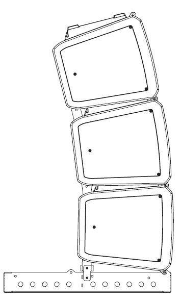
Flown Deployment
The sections below give examples for flying PL Series loudspeakers.
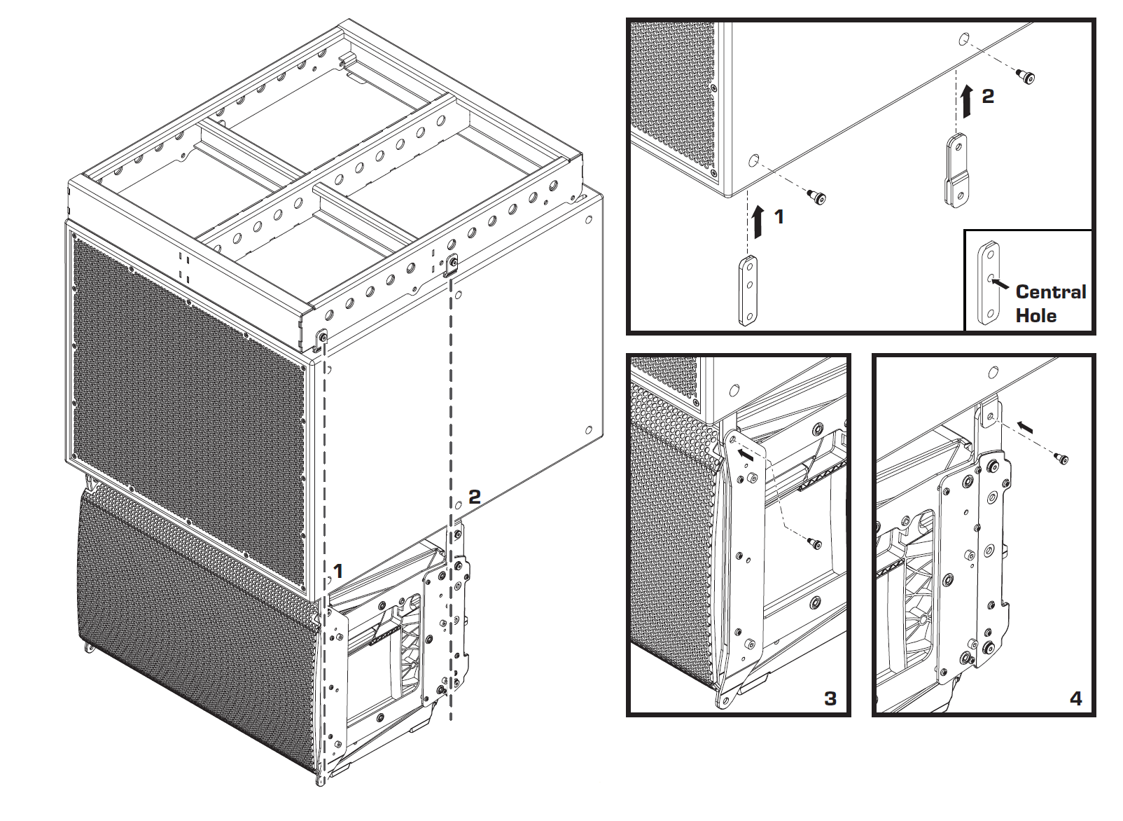
Attaching PL-LA to the Array Frame PL-AF

Downtilt (Normal Frame)
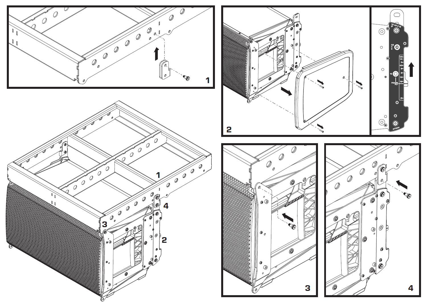
Uptilt (Reverse Frame)
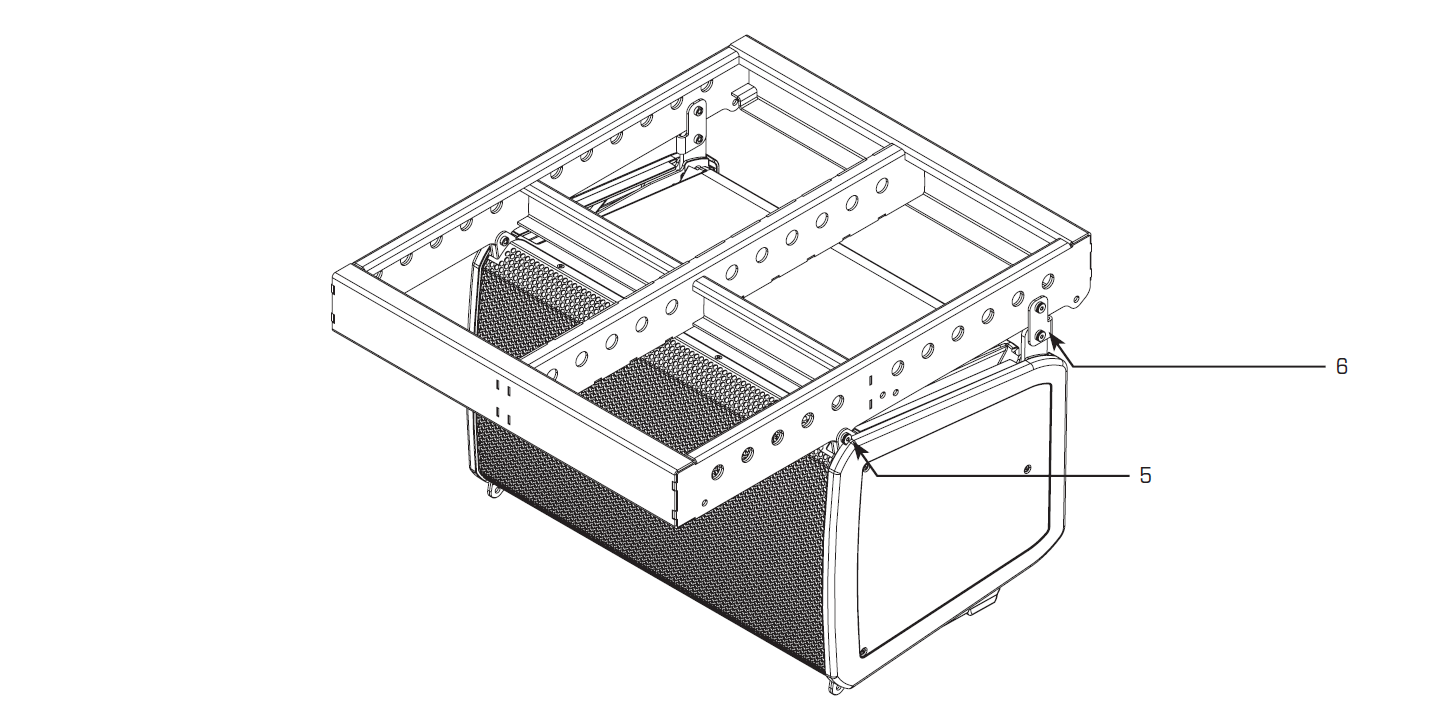
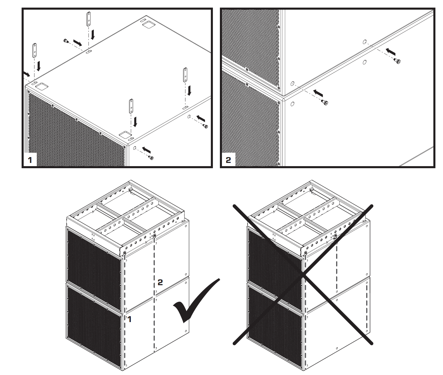
Attaching PL-LA to PL-LA
Note
Do not fully torque the screws before the array is mounted and angled, as it will prevent the free rotation needed so gravity can set the angle as needed.

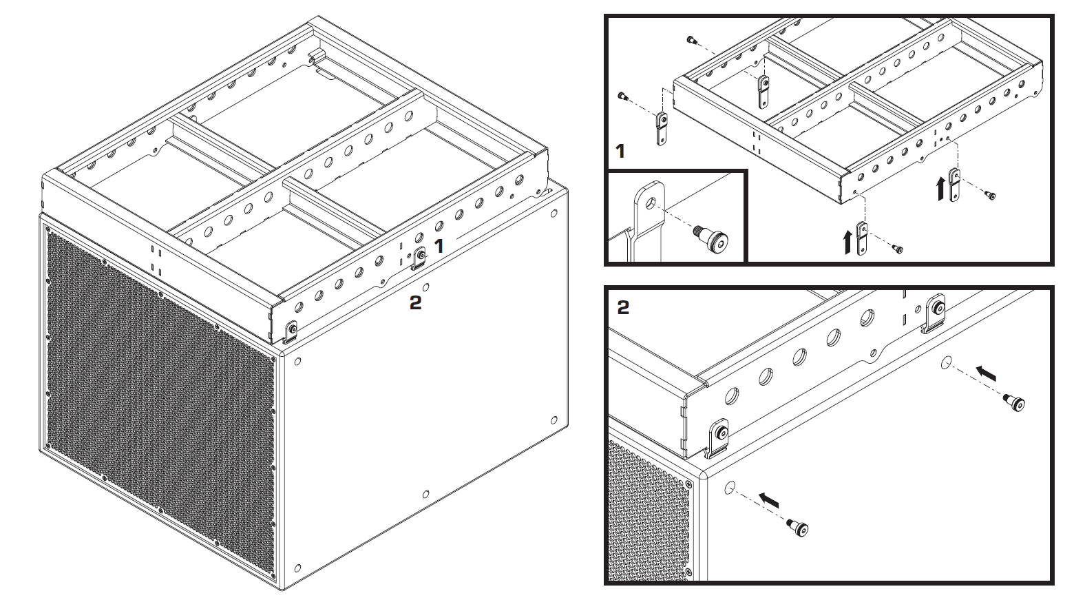
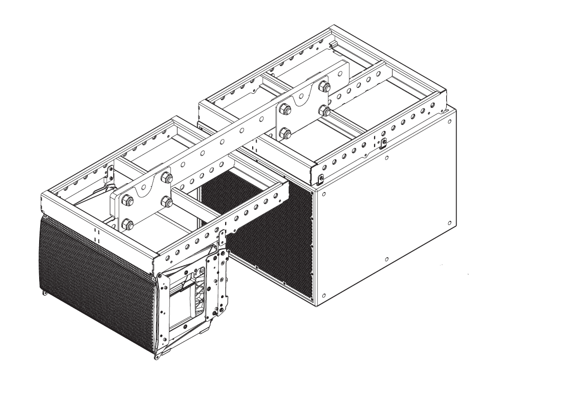
Attaching a PL-SUB18 to the PL-LA12-AF Array Frame
Attaching a PL-LA12 under a PL-SUB18
Attaching a PL-SUB18 under a PL-SUB18
Pullback Bar
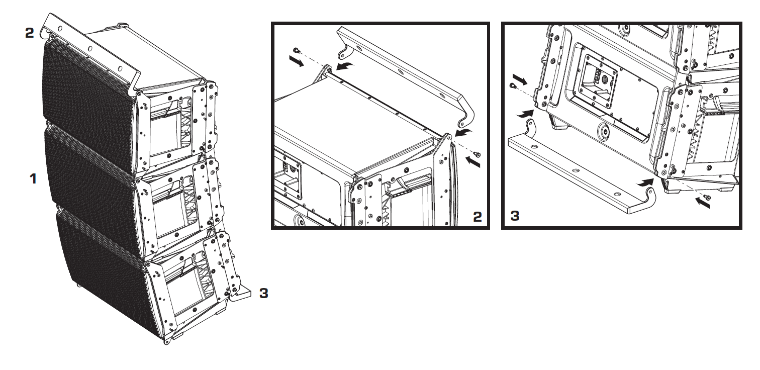
Safety Precautions when using a Pullback Bar
- The load angle with the vertical at the attachment point should be between 0° and 45°
- Only use pick-point numbers 1 to 6 on the Array Frame.
- Limit Frame Angle (see figure)

EB3082 Extension Bar
Warning
Do not tilt more than +/-5°
Ground Deployment
The sections below give examples for ground/stacked installations for PL Series loudspeakers.
Stacking two PL-SUB18

Stacking a PL-LA on a Array Frame
Note
See “Flown Deployment / Attaching PL-LA to the Array Frame PL-AF” for details on assembly.
Single Loudspeaker Deployment
The sections below give examples for single speaker installations for PL Series loudspeakers.
LA-KIT-I Accessory
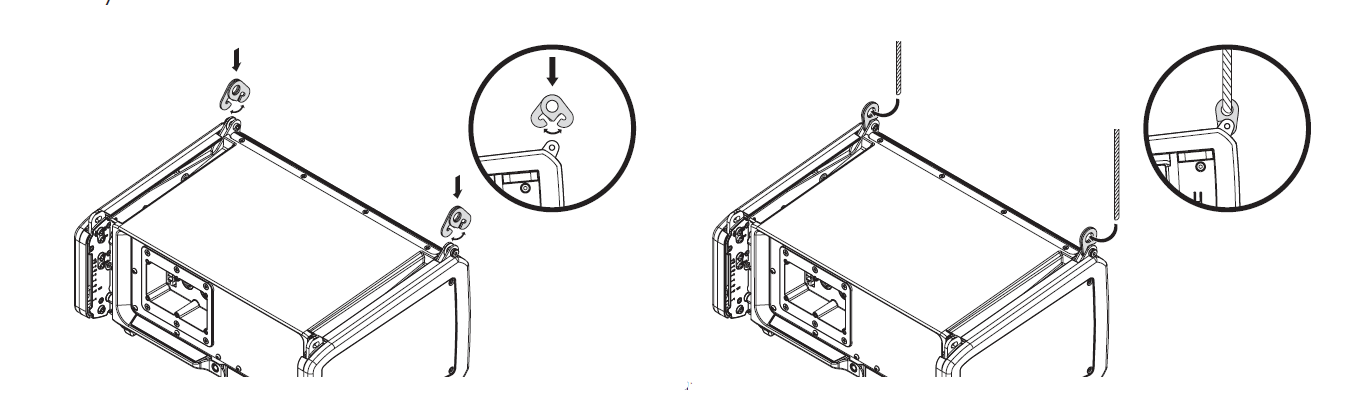
Flying a single PL-SUB18 without Array Frame
Attach four 1/4 in. shackles with an 8 mm pin shaft to the Straight Links in a straight position.