How To | Create a ringing LED that only acts on incoming calls
Learn how to use an LED circuit to create a ringing visual indicator for incoming calls.
Procedure
The status of the ringing LED in the Softphone Status/Control block is TRUE in both incoming and outgoing calls. Some users, though, understandably prefer to have an LED indicator on incoming calls but not outgoing ones. A custom control in the Q-SYS design can do this. The procedure below describes how to construct it.
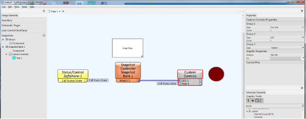
- Drag the Softphone Call Status component onto the design and enable the State control pin. The State control produces a string that describes the state of the call: inactive, active, outgoing, or incoming.
- Create a Custom Controls block.
- In Group 1, select a Text edit type control on it.
- In Group 2, select an LED type control.
- Tie the State control pin of the Softphone Status/Control component to the Text 1 input control pin of the Custom Controls component.
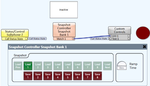
- Create a new Snapshot Bank.
- Drag the Text Edit box onto it.
- Drag the Snapshot Bank component onto the design.
- Enable the Match 1 control pin and tie it to the LED 1 control input pin.

- To run the design in emulation, click File > Emulate or press F6.
- If the design is part of an active Q-SYS system, you can save it to the Core Processor (click File > Save to Core & Run or press F5).
- Type
incomingin the Text box. - Open the Snapshot Bank component and click Save 1.

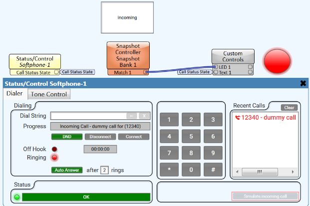
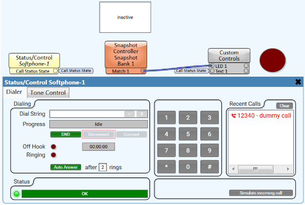
Now whenever the call state is incoming, the Match 1 output will activate LED 1. In a Q-SYS system you can verify this with an actual incoming call, or you can simulate its operation by opening the Softphone Status/Control component and using the Simulate incoming call and Disconnect buttons.

